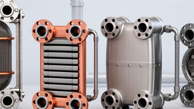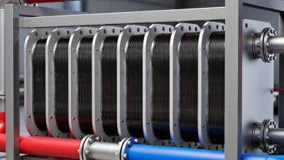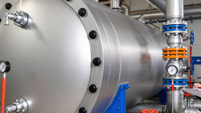
Choosing a Heating Plate Heat Exchanger is often a practical decision: save floor space, manage heat efficiently, and simplify maintenance. Inside its frame, thin metal plates create narrow channels for two fluids. Heat passes across the plates while the fluids remain separate. The result can be a compact unit suited to heating systems, process water, and many industrial duties.
Professor S. K. Som is a heat-transfer educator and author. The following line is an editorial paraphrase of established heat-transfer principles, not a verified verbatim quotation: “Good exchanger design matches heat-transfer needs with pressure drop, fluid properties, and maintenance demands.” That balance matters. A plate unit may offer strong thermal performance, but it is not automatically the right choice for every system. Gasket compatibility, operating pressure, fouling, and cleaning access all deserve attention.
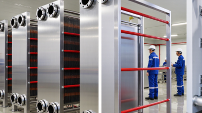
Picture a technician opening the frame and inspecting the plate pack. That straightforward access can make routine service easier, provided the design and installation allow it. Small details count. Plate material must suit the fluid, and the channel arrangement must support the required flow. A poor match can reduce efficiency or increase maintenance.
This guide examines why buyers choose a Heating Plate Heat Exchanger, where it performs well, and what to check before specifying one. Real operating conditions matter more than brochure claims. Even a well-designed unit needs thoughtful sizing and regular inspection.
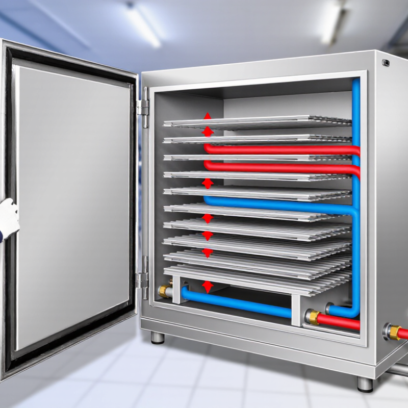
A heating plate heat exchanger is a device that transfers heat between two fluids without mixing them. It contains a stack of thin, corrugated metal plates held together in a frame or sealed as a compact unit. The plates form narrow channels. Hot water or another heating fluid flows through alternating channels, while the cooler fluid passes through the others. Heat crosses the metal surface as the fluids move in opposite or parallel directions. That separation matters.
In a building, the unit might transfer heat from a boiler loop to water circulating through radiators or a floor-heating system. The exact performance depends on fluid temperatures, flow rates, plate design, and pressure drop. Narrow channels create plenty of contact area, but they can collect scale or debris if the water is poorly maintained. The terminology can be confusing: gasketed, brazed, and welded models use different methods to seal the plates, so they are not interchangeable in every installation. Small details count. Engineers typically check operating conditions and maintenance access before selecting a unit; the name alone does not tell you whether it fits a particular system.
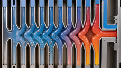
A heating plate heat exchanger transfers energy through thin metal plates. Hot and cold fluids travel through alternating channels, separated by the plate walls. Heat passes through the metal, while the fluids normally remain apart. Corrugations in the plates add surface area and guide the flow. They can also create turbulence, which helps heat move efficiently. That detail matters. A damaged plate or failed seal can allow fluids to mix, so inspection is essential.
Many units arrange the streams in opposite directions. This counterflow pattern helps maintain a useful temperature difference along the exchanger. For example, warm water can transfer heat to a cooler process fluid as both move through narrow channels. Actual performance depends on flow rate, fluid properties, plate condition, and fouling. Deposits can build up in small passages and reduce heat transfer. Cleaning intervals should match the application; a fixed schedule may not suit every system.
Tips: Check operating temperatures and pressure limits before selection. Keep strainers clean, and inspect for leaks or uneven heating. Record performance over time. Measurements can reveal problems, though they rarely tell the whole story.
Why Choose a Heating Plate Heat Exchanger?
Which Design Features Affect Heating Performance
A heating plate heat exchanger can deliver fast, controlled heat transfer in a compact space. Its performance depends on more than plate count. Plate shape and corrugation create turbulence, helping heat move between fluid channels. Deeper corrugations may improve heat transfer, but they can also increase pressure drop. The best balance depends on available pump capacity and the required heating duty.
Channel width matters, too. Narrow passages can increase fluid velocity and heat transfer, yet they may be more sensitive to debris or scale. Plate area, material thickness, and flow arrangement also affect performance. Counterflow layouts often maintain a useful temperature difference along the exchanger. In practice, even a well-designed unit can underperform if flow rates, inlet temperatures, or fluid properties differ from the design assumptions. That detail is easy to miss.
Tips: Check the fluid temperatures, flow rates, and pressure limits before selecting a unit. Ask about cleaning access and compatible plate materials. Keep an eye on outlet temperatures during operation. Small changes can signal fouling, though they do not prove it.
| Design Feature | Typical Values or Options | Effect on Heating Performance | Selection Considerations |
|---|---|---|---|
| Plate corrugation angle | Chevron angles commonly fall within approximately 30°–65°. | Higher-angle patterns generally promote stronger turbulence and heat transfer, but also increase pressure drop. Lower-angle patterns typically reduce flow resistance. | Balance heat duty against the available pump head. Mixed-angle plate arrangements can help balance heat transfer and pressure drop. |
| Heat-transfer surface area | Set by plate count, plate size, and the required heating duty. | More effective area can support the required duty or a closer outlet-temperature approach, provided the flow distribution and operating conditions are suitable. | Size from the fluid flow rates, inlet and target outlet temperatures, fluid properties, and allowable pressure drops—not plate count alone. |
| Plate material and thickness | Common plate materials include stainless steel and, for some corrosive services, titanium or other corrosion-resistant alloys. Plate thickness is often about 0.4–0.8 mm, depending on design. | Thinner plates can reduce conduction resistance; material choice affects corrosion resistance, durability, and suitability for the process fluid. | Confirm chemical compatibility, temperature and pressure limits, and water quality. Material selection should be based on the actual fluid composition. |
| Channel gap and flow arrangement | Channel geometry and the number of channels per pass vary by model and duty. Counter-current flow is commonly used for heating. | Counter-current flow can achieve a closer temperature approach than parallel flow in many applications. Channel geometry affects velocity, heat transfer, and pressure loss. | Check flow distribution and channel velocity at both normal and turndown conditions. Avoid designs that create excessive pressure drop or poor distribution. |
| Operating flow rate | Must be specified separately for the heating and heated-fluid sides. | Flow rate influences channel velocity and heat-transfer coefficients. A higher rate may improve heat transfer but can raise pressure drop and pumping demand. | Use the full operating range, including minimum and peak flows, when selecting the plate pack and control strategy. |
| Temperature approach | Close approaches of a few degrees Celsius may be achievable in suitable designs; the required value depends on the fluids and operating conditions. | A smaller approach generally requires more heat-transfer area and can affect both equipment size and cost. | Specify hot-side inlet temperature, cold-side inlet temperature, and target outlet temperatures for thermal sizing. |
| Allowable pressure drop | Set independently for each side; practical limits depend on the system and pump. | Allowing more pressure drop can permit a more compact, higher-transfer design, but increases pumping energy and may exceed system limits. | Include pipework, valves, strainers, and other system losses when determining the pressure-drop budget. |
| Fouling allowance and cleanability | Depends on fluid cleanliness, scaling tendency, suspended solids, and maintenance method. | Deposits add thermal resistance and can narrow flow passages, reducing heat output while increasing pressure drop. | For fouling-prone services, consider filtration, suitable channel geometry, cleaning access, and an appropriate maintenance schedule. |
| Gasket and frame design | Gasket material and frame configuration must suit the operating temperature, pressure, and fluid. | Gaskets provide sealing and allow access for inspection or cleaning in many gasketed designs; their limits affect operating suitability. | Verify gasket compatibility and the manufacturer’s rated temperature and pressure limits for the selected configuration. |
Note: Values and options shown are general engineering guidance, not guaranteed ratings. Final heating performance depends on the selected unit, fluid properties, fouling conditions, and specified operating points.
In a heating system, a plate heat exchanger transfers energy between two fluid circuits without mixing them. Thin, corrugated plates provide a large heat-transfer area in a compact unit, which can free valuable plant-room space. Space matters. For example, a facility upgrading a boiler loop may fit a plate unit beside existing pumps instead of expanding the mechanical room.
Plate units can support close temperature control when flow rates and operating temperatures are selected carefully. This is useful in domestic hot-water preheating, hydronic heating, and process-water circuits. A gasketed design can be opened for inspection or expanded with additional plates, helping when future capacity needs are uncertain. But the benefit depends on the fluid. Sludge, scale, or fibrous particles can foul narrow channels and reduce performance.
Good selection starts with actual operating data: inlet and outlet temperatures, flow, pressure, fluid chemistry, and allowable pressure drop. A smaller exchanger is not automatically better; undersizing may leave rooms slow to warm, while excessive pressure loss can increase pump demand. Maintenance access deserves attention too. Details matter. Even a well-designed unit needs periodic checks, and gasket condition can change with heat and age. These points are easy to overlook during a quick equipment comparison.
A heating plate heat exchanger should be selected around real operating conditions, not just its advertised capacity. Record inlet and outlet temperatures, flow rates, fluid properties, and maximum expected pressure. Include seasonal changes; a system running gently in spring may face a much larger load in winter. Check the allowable pressure drop, since narrow passages can restrict flow and increase pumping demand. For dirty or viscous fluids, wider plate channels may reduce blockage, though they can affect heat transfer. Choose plate and gasket materials suited to the fluid and temperature range. Small details matter. Request a duty calculation, and question assumptions that seem unusually neat. Even a careful estimate can miss how variable real fluid conditions are.
During commissioning, note temperatures, pressure readings, and visible leak points as a baseline. Later, compare readings; reduced performance or rising pressure drop can signal fouling. Before opening the unit, isolate it, let it cool, and release pressure according to site procedures. Clean plates with methods approved for their materials; harsh tools can damage sealing surfaces. Inspect gaskets for flattening, cracks, or movement, and replace damaged parts rather than tightening blindly. Reassemble evenly and follow the specified tightening dimension. Check carefully. Keep a service log with dates, readings, and cleaning details. Record units clearly, since inconsistent notes can hide a developing problem.
Calculated heating duty increases with water flow when the temperature rise is held constant at 20°C.
Calculated using water density of approximately 1 kg/L and specific heat capacity of 4.18 kJ/(kg·°C). Actual exchanger performance depends on flow conditions, temperatures, fouling, and equipment design. When selecting and maintaining a unit, check the required duty, pressure drop, material compatibility, and signs of fouling or leakage.