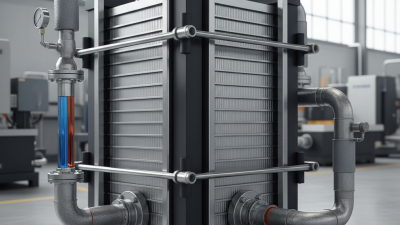
An Inside Heat Exchanger connects the refrigeration system’s liquid line and suction line. It transfers heat internally, without mixing the two refrigerant streams. Warm, low-pressure suction vapor absorbs heat from the cooler, high-pressure liquid. The liquid becomes more subcooled before entering the expansion device. The suction vapor becomes slightly superheated before reaching the compressor.
This small component can influence system stability, capacity, and compressor protection. ASHRAE Handbook—Refrigeration describes liquid-suction heat exchange as a practical method for increasing liquid subcooling and suction-gas superheat. However, its value depends on the refrigerant and operating conditions. Added suction-line heat may increase compressor work. Pressure drop can also reduce expected gains. The answer is not always yes.
The wider energy context makes this assessment important. The International Energy Agency reported in The Future of Cooling that space-cooling electricity demand could more than triple by 2050 without stronger efficiency improvements. In a supermarket case, an Inside Heat Exchanger may help maintain stable liquid conditions while refrigerant travels through a long pipe. You might see the effect as a colder liquid line and a warmer suction line. That physical detail matters.
Still, a clean diagram can hide real losses. Engineers should compare measured subcooling, superheat, pressure drop, compressor power, and seasonal efficiency. Field experience often reveals what simulations miss. Installation quality matters too. Poor insulation can erase part of the benefit. The best design is not simply the hottest suction gas or coldest liquid. It is the most balanced result for the complete refrigeration cycle.
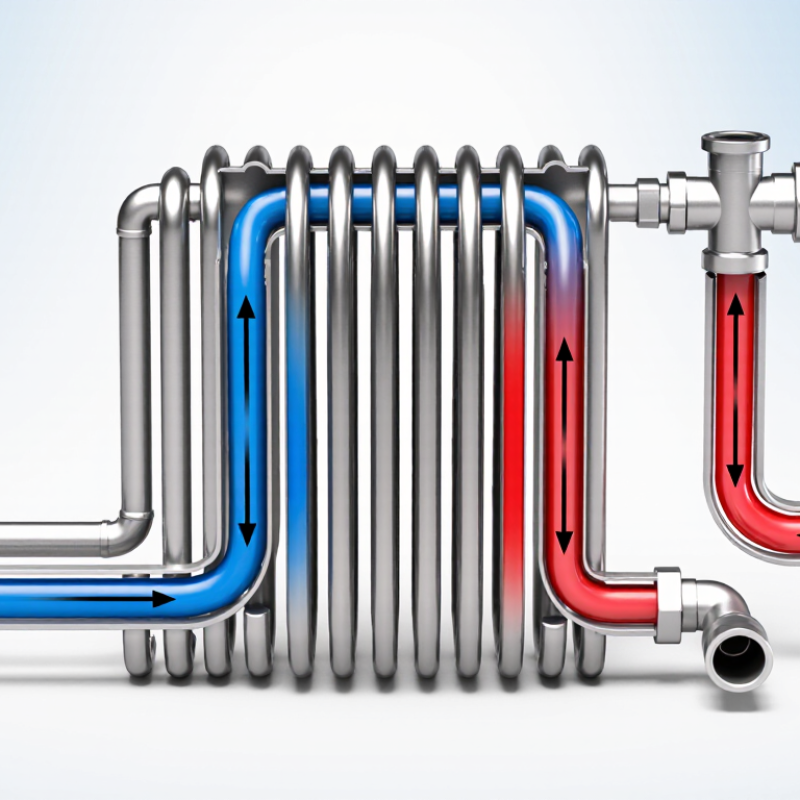
In a refrigeration cycle, an inside heat exchanger (IHX) is a refrigerant-to-refrigerant heat exchanger installed inside the system. It usually connects the liquid line leaving the condenser with the suction line returning to the compressor. The two refrigerant streams do not mix. Heat passes through a metal wall instead. Simple hardware, important job. As the warm liquid gives up heat, it becomes more subcooled before reaching the expansion device. At the same time, the cool suction vapor gains superheat before entering the compressor.
This arrangement can reduce flash gas after the expansion valve. More liquid may reach the evaporator, supporting steadier evaporator performance. Extra suction superheat also helps protect the compressor from liquid return when load conditions change quickly. During commissioning, technicians should check liquid temperature, suction temperature, and pressure on both sides. A temperature reading alone can mislead you. Pressure-based saturation temperatures are needed to calculate actual subcooling and superheat.
The IHX is not automatically beneficial. Suction vapor leaves hotter, so compressor discharge temperature may rise. That can reduce efficiency in some systems, especially when the temperature lift is already high. A poorly sized exchanger may add pressure drop or provide little useful transfer. The trade-off deserves measurement, not assumption. Some designs look excellent on paper, then perform differently after piping, airflow, or charge conditions change. That gap is worth investigating.
An inside heat exchanger moves heat between two refrigerant lines without mixing their contents. In a common arrangement, warm, high-pressure liquid leaving the condenser passes beside cool, low-pressure vapor returning from the evaporator. Heat flows through the metal wall from the liquid to the suction vapor. The liquid becomes subcooled, while the vapor gains superheat before reaching the compressor. The pipes stay separate. Only heat crosses between them.
This exchange can reduce flash gas before the expansion device and help ensure vapor, rather than liquid, enters the compressor. The practical result depends on the refrigerant, operating conditions, and exchanger design. More heat transfer is not always better: added suction superheat may raise compressor discharge temperature, and pressure drop can offset some gains. A measured temperature change matters more than assumptions. Real systems can be a little less tidy than diagrams suggest.
Tips: Compare liquid and suction temperatures at the exchanger inlet and outlet, using stable operating conditions. Check for unusual pressure drop and confirm the compressor’s temperature limits. Small readings can mislead; sensor placement and insulation matter. If performance changes, consider the whole system, not just this component.
How Does an Inside Heat Exchanger Work?
How 5–15 K of Liquid Subcooling Improves Expansion-Valve Performance
An inside heat exchanger transfers heat from the warm, high-pressure liquid line to the cool suction vapor returning from the evaporator. The liquid arrives at the expansion valve colder, while the suction vapor gains heat before reaching the compressor. That exchange can reduce flash gas at the valve inlet. Less vapor in the liquid stream gives the valve a steadier supply of refrigerant.
The effect is measurable. For a refrigerant with liquid specific heat near 1.4 kJ/kg·K, 5–15 K of additional subcooling adds roughly 7–21 kJ/kg of liquid enthalpy reduction. This is an illustrative estimate; actual values vary by refrigerant and operating pressure. ASHRAE Handbook—Refrigeration explains how subcooling increases the refrigerating effect per unit mass. More useful capacity can result without increasing refrigerant flow. Small change. Yet an inside heat exchanger also warms compressor-bound vapor, so discharge temperature may rise. Check it under real load, not just at steady laboratory conditions. The trade-off is easy to overlook. A 10 K subcooling gain does not guarantee a 10% efficiency gain; compressor type, ambient temperature, charge, and heat-exchanger sizing all matter. Measure liquid temperature at the valve inlet and suction temperature near the compressor. Then compare capacity and power at matched conditions.
How 5–15 K of liquid subcooling can improve expansion-valve performance
An inside heat exchanger transfers heat from the high-pressure liquid line to the low-pressure suction vapor. The resulting liquid subcooling lowers liquid enthalpy before the expansion valve, helping reduce flash gas at its inlet and support more stable valve feeding. Bars estimate the liquid enthalpy reduction using a constant liquid specific heat capacity of 1.4 kJ/(kg·K); actual values depend on the refrigerant and operating conditions.
How Does an Inside Heat Exchanger Work?
How 20–50% Heat-Exchanger Effectiveness Affects System Efficiency
An inside heat exchanger transfers heat between warm liquid refrigerant leaving the condenser and cool vapor returning from the evaporator. This subcooling and superheating happen inside one insulated assembly. Effectiveness measures how closely the exchanger approaches its maximum possible heat transfer. At 20% effectiveness, temperature changes are modest; at 50%, they are larger, but not automatically better for the system.
Consider liquid refrigerant entering at 40°C and suction vapor at 10°C. If the exchanger’s maximum possible temperature change is 30°C, 20% effectiveness corresponds to roughly 6°C of heat transfer temperature change; 50% corresponds to 15°C. These are illustrative values, not guaranteed savings. The added subcooling may increase refrigeration capacity, while extra suction superheat can raise compressor work and discharge temperature. ASHRAE’s Handbook—Refrigeration explains these competing effects in vapor-compression systems. AHRI Standard 540 provides a recognized framework for rating refrigerant compressors, but actual efficiency must be checked at the system’s operating conditions.
The trade-off is tangible: a warmer compressor inlet pipe can signal useful heat recovery, or excessive superheat. Small changes in refrigerant charge, airflow, and load can shift the result. I would not choose a 50% effective exchanger by default; measure capacity, power draw, and discharge temperature across the expected operating range. A single design point can mislead.
How Does an Inside Heat Exchanger Work?
An inside heat exchanger (IHX) transfers heat between liquid refrigerant leaving the condenser and cool vapor returning from the evaporator. The liquid becomes slightly cooler, while the suction vapor gains superheat. This can reduce flash gas before the expansion device and help protect the compressor from liquid return. But the gain is not automatic. Added tubing and tight passages create pressure drop on both sides, which can reduce capacity and increase compressor work. ASHRAE’s 2022 Handbook—Refrigeration treats pressure loss and suction conditions as key refrigeration-system design factors. Designers should assess them together, not judge an IHX by heat-transfer area alone.
The trade-off is visible in the gauges: a small suction-line pressure loss can lower compressor inlet pressure, while excessive superheat raises discharge temperature. The acceptable limit depends on the refrigerant and compressor; manufacturer operating envelopes and refrigerant property data should guide the final check. A useful design comparison records evaporator outlet superheat, compressor-inlet pressure, discharge temperature, and system capacity with and without the IHX. Real systems vary. That is worth remembering.
Tips: Keep the suction passage short and adequately sized. Check pressure drop at peak mass flow, not just nominal conditions. Confirm that added superheat stays within the compressor’s specified operating range.
| Design dimension | What happens | Typical design consideration | Practical implication |
|---|---|---|---|
| Heat-exchange arrangement | High-pressure liquid leaving the condenser transfers heat to low-pressure vapor returning from the evaporator. | The two refrigerant streams are separated by a heat-transfer wall; they do not mix. | The liquid is subcooled while the suction vapor is superheated. |
| Liquid-side subcooling | Heat removed from the liquid lowers its temperature below the saturation temperature at the liquid-side pressure. | Subcooling depends on refrigerant, mass flow, inlet conditions, exchanger size, and operating load. | Additional subcooling can reduce flash gas formation after the expansion device, but its benefit must be weighed against suction-side effects. |
| Suction-side superheat | Returning vapor gains sensible heat as it passes through the exchanger. | Check compressor-inlet temperature and the compressor manufacturer's allowable operating envelope. | Excessive superheat can raise discharge temperature and reduce refrigerant mass flow or system capacity, depending on the system. |
| Suction pressure drop | Friction and flow disturbances reduce pressure between the evaporator outlet and compressor inlet. | Evaluate pressure drop at expected minimum and maximum mass flow, not only at one rated condition. | Lower compressor-inlet pressure can increase compression ratio and reduce capacity and efficiency. |
| Liquid-side pressure drop | Flow resistance lowers liquid pressure before it reaches the expansion device. | Keep the liquid pressure high enough to avoid unwanted flashing upstream of the metering device. | Excessive pressure loss can impair liquid delivery and offset some benefits of subcooling. |
| Heat-exchanger effectiveness | A larger heat-transfer area or stronger heat transfer can increase exchange between the two streams. | Thermal performance must be assessed together with pressure losses, superheat, refrigerant properties, and load range. | Maximizing heat transfer alone may produce an unsuitable design if pressure drop or compressor-inlet temperature becomes excessive. |
| Operating conditions | Refrigerant properties and mass flow change with evaporating and condensing conditions and system load. | Check the full operating envelope, including part-load operation and expected ambient conditions. | A design that performs well at one rating point may not meet pressure-drop or superheat limits elsewhere. |
| System-level assessment | The exchanger changes both liquid and suction conditions and therefore affects the refrigeration cycle as a whole. | Compare predicted capacity, power, discharge temperature, and stability with and without the exchanger. | The net benefit is system-dependent; use refrigerant-specific calculations and verify against equipment limits. |